Hardware Installation
Table of Contents
Preparation
- Install the brass standoffs onto the Raspberry Pi so that they are ready to support the power monitor PCB after install.
Show picture:
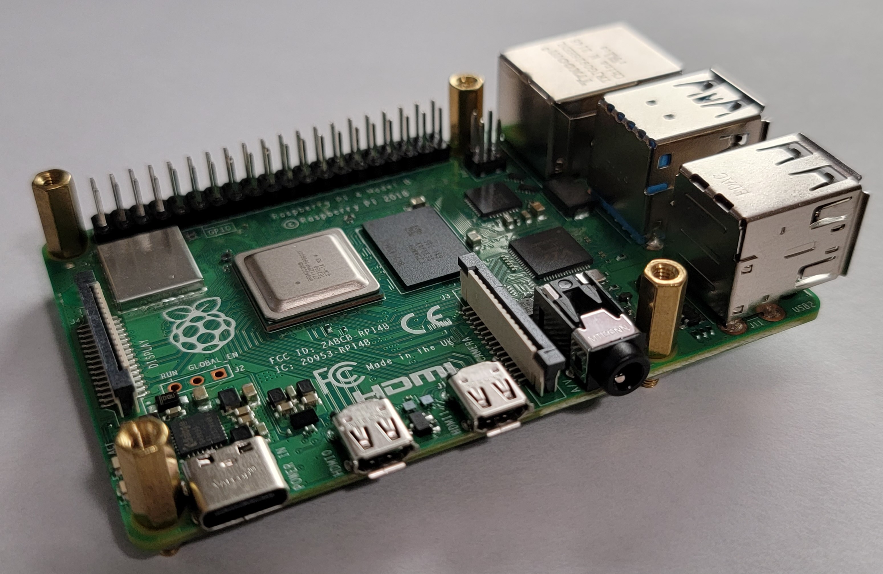
- Make sure you’ve already done the channel configuration part of the software installation so that you can get straight to post install verification.
Panel Installation
This project should be installed by a licensed electrician. Your electrical panel is still energized, even with the main breaker shut off! You can be seriously or fatally injured if you are not competent and confident in electrical safety.
You’ll need the following for installation:
- AC clamp current meter
- Multimeter
- Mini flat-head screw driver (for the factory assembled PCB terminal screws)
- Mini Phillips-head screw driver (for the standoff screws)
Panel installation is intended for whole home monitoring implementations. From the planning step, you should have identified a place to install the power monitor and identified the breakers that you intend to monitor.
Simply clamp each sensor around the hot wire for the target circuit, and run the sensor wire back to the location of the Raspberry Pi. The sensor wire should be kept as far away from the high voltage conductors as reasonably possible to minimize interference and noise. Take note of which sensor wire is which so that you can validate the channel configuration after install.
On the factory assembled PCB, do not over tighten the screws in the terminal block. Once they start to get tight, they should be tight enough.
On the DIY kit PCB, you should already have an understanding of how the sensor wires connect to the PCB either via the RJ-45 jack or the two 3.5mm jacks. If not, see here.
After the sensor wires are connected to the PCB, slide the PCB onto your Raspberry Pi’s header pins, so that the power monitor PCB sits over the Raspberry Pi. Then, use the four screws from the standoff set to secure the PCB to the Pi.
Connect the 9V AC transformer to the nearest outlet, and plug the cable into the jack on the PCB.
Post Install Validation
After the sensors have been safely installed in the panel, you’ll need to check the readings for each of them. Turn the electrical panel back on, and power on your Pi.
Login to your Pi, and start the software in terminal mode with the following command:
python3 ~/rpi_power_monitor/rpi_power_monitor/power_monitor.py --mode terminal
This will display a table in your terminal with the latest measurements for each sensor.
It is important to make sure the sign of the Watts field is correct for the application:
- All
consumptionchannels should read positive Watts. - All
productionchannels should read positive Watts when producing. - The
mainschannels should be positive if you do not have any production sources, or if those production sources are not producing. If you have grid-tied solar panels, you’ll probably need to wait until dark to confirm this (or shut down your solar inverter).
If any values have the wrong sign, you can change the reversed setting for the channel in config.toml. you can reverse the polarity of the CT sensor wires at the PCB. If you can’t reverse the polarity at the PCB (such as with the DIY kit’s RJ-45 or 3.5mm interfaces), you can unclip the CT and reverse the direction that it is clipped around the conductor.
The net power and home power calculations both rely on proper signage according to the above parameters! If your net power figures do not make sense, double check that your production sources are showing positive Watts when producing. Then, check that your mains are showing positive Watts when you’re not producing any power (such as at night, for solar panels).
After validation, move onto the Calibration (v0.3.0) section.
Single-Appliance Installation
If you are using the power monitor to measure an individual appliance, there’s one obstacle in doing so: you can’t use the sensor over the entire power cable. The sensor must only be installed over the “hot” wire of the cable, excluding the ground and neutral wires. Because most power cables have multiple conductors inside them, this makes it tricky to install for a single appliance. You’ll likely need to make your own extension cable to get access to the hot conductor inside the cable. Here are some components you can use to make a custom extension cable. If your load is over 10A continuous, you should go with a 14-gauge cable instead.
Making custom cables can be dangerous and increase the risk of shock. Do not attempt to modify cable that is energized!